
 Apr 01,2024
 BOMI SHANGHAI
 30
30
As automotive competition in China intensifies and customer expectations rise, design validation tools are evolving fast. Among them, full-scale clay models used in wind tunnel testing have emerged as a critical asset for optimizing vehicle aerodynamics and acoustics. These models allow development teams to visualize, refine, and verify design proposals with scientific precision—all before a single production tool is made.
This article documents the process of designing and fabricating a full-size wind tunnel clay model developed during the X95 project, revealing the techniques and lessons learned from concept to completion.
A wind tunnel clay model is a full-scale physical prototype designed for aerodynamic and acoustic testing in a controlled environment. It features a sculpted clay surface, supported by a precision-engineered internal frame, and is subjected to high-speed airflow to assess drag, turbulence, and noise levels. These test results help refine the final vehicle design and ensure better performance on the road.
Strength and Precision: The internal frame is constructed from circular and rectangular steel tubing, designed to maintain rigidity under transportation and testing conditions. Key areas are reinforced with 15mm-thick datum blocks and undergo stress-relieving treatments to eliminate internal distortion.
Coating and Marking: Non-locating surfaces are coated with anti-rust black or yellow paint. Critical alignment points are clearly marked with coordinate plates for accurate positioning.
Mobility and Modularity: Components like wheels are mounted on adjustable axes with a minimum ±30mm range to simulate various driving conditions. Auxiliary subframes are detachable for added support during long-distance transport.
Testing Alignment: The frame includes provisions for accurate repositioning during multi-stage testing and multiple clay re-applications.
Durability Under Wind Load: Clay thickness is maintained above 30mm across the surface to resist deformation at wind speeds of up to 140 km/h.
Aerodynamic Fixtures: All grilles, underbody panels, and air deflectors are removable, sealed, and correctly positioned for airflow simulation. Engine bay parts such as radiators and fans are mounted as real components, while other assemblies use high-fidelity mockups.
Acoustic Treatments: The model includes a sealed acoustic cabin with dual-layer wooden panels and embedded EVA foam for interior noise testing. Custom microphone mounts are also integrated into the driver’s cabin.
Attachment Standards: Exterior components like mirrors and wheel housings are designed for fast removal and reassembly on-site. Structural integration ensures repeatability without compromising the model’s geometry.
The entire model design was developed using Unigraphics NX 12, a professional CAD/CAM software suite. Using Class-A surface data and modular segmentation, engineers crafted the frame layout, ensured mechanical clearances, and anticipated component interference.
Each section of the frame was CNC-machined after welding and treated for corrosion resistance. To prepare for high-accuracy finishing, the layout incorporated both styling and functional zones, with reserved space for secondary machining and alignment fixtures.
The process unfolded in the following stages:
Frame Fabrication: Steel tubes were assembled into a rigid base structure.
Acoustic Chamber Assembly: Modeled closely after a real driver’s cabin, featuring sealed compartments with layered soundproofing.
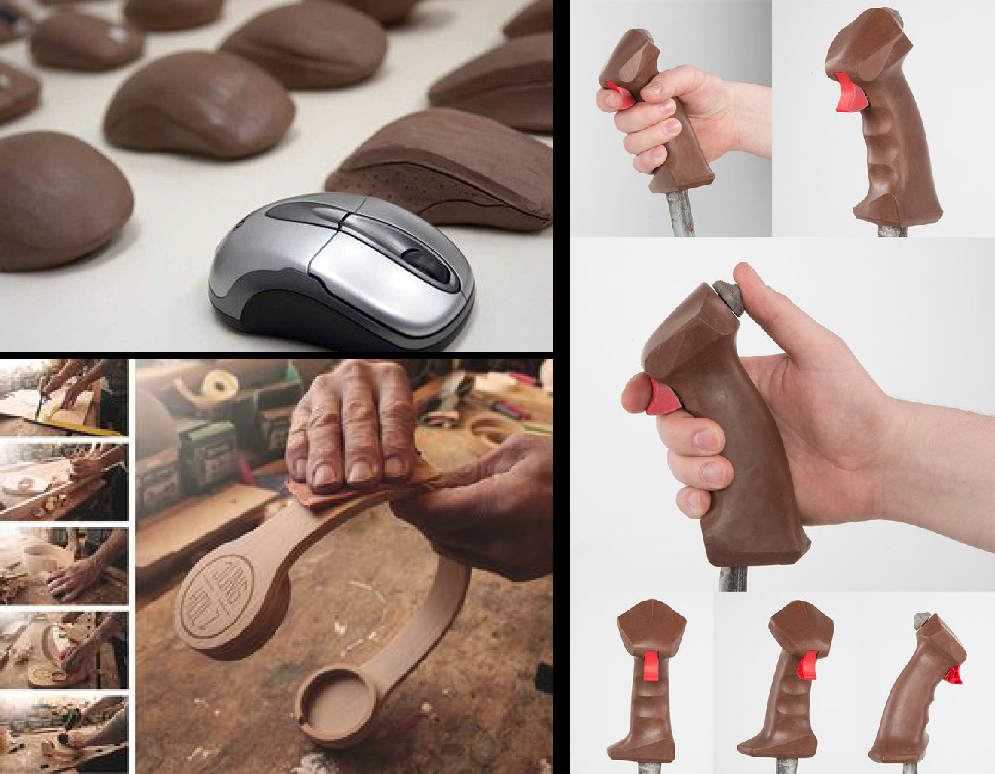
Foam and Panel Bonding: Foam blocks were cut and bonded to the structure using adhesives; composite panels were mounted with bolts.
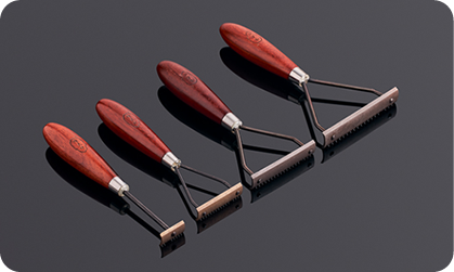
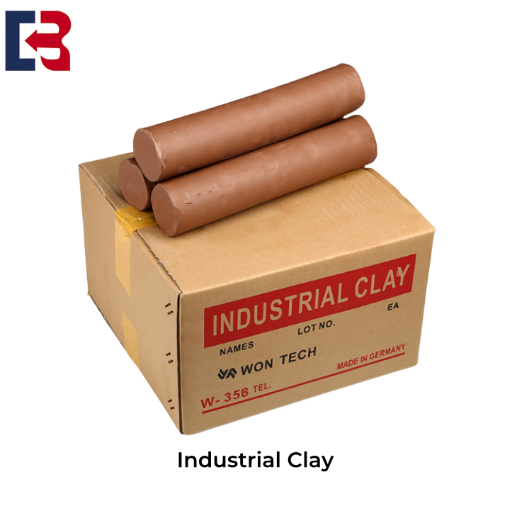
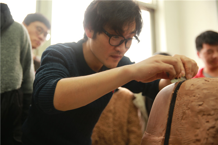
Clay Application: Clay was applied over the foam and sculpted to match surface data, with a focus on achieving seamless contours.
5-Axis CNC Finishing: Once the clay hardened, the model underwent full-surface machining. A large-radius custom ball end mill (R10) was used for finishing with a 3mm step-over and 0.1mm machining allowance.
Component Integration: After the sculpting phase, accessories such as hoods, mirrors, grilles, wheels, and glass were installed to complete the model.
Final Inspection: Surface smoothness, part fitment, tire positions, and engine bay alignments were thoroughly verified.
This wind tunnel clay model project marks a significant step forward in in-house model-making capabilities. The design team successfully:
Increased aerodynamic model accuracy
Reduced CNC machining time
Improved test site efficiency using quick-swap modules
The model delivered valuable aerodynamic and acoustic data under real-world simulation, reinforcing the value of physical prototyping even in a digital-first era.
Although domestic model-making capabilities are approaching international standards, further improvements in data feedback loops and modular database development are needed. As experience accumulates, the performance gap with leading global firms will continue to narrow.